Tuesday, October 26, 2010

The Addressing Modes in the MSP430 Family


Register Mode


mov.w R4,R5 ; move (copy) word from R4 to R6

It is the fastest, with only 1 machine cycle needed.
Any of the 16 registers can be used as source or destination.

Special cases:
  • PC - it will be autoincremented before it is used as source
  • Both PC and SP must be even, because they are always used as words. so  LSB discarded if they are used as destination
  • CG2 - it reads 0 as source
for byte operations:
  • operand is taken from lower byte only
  • writing is performed to lower byte only, upper byte is cleared
To use the upper byte in a regiser as source, 'swpb' may be used.

Indexed Mode 

Similar to arrays.

mov.b 3(R5),R6 ; load byte from address 3+(R5) into R6

Here, base address is 3.
Indexing can be used for the source or destination part.

Symbolic Mode (PC Relative)

When PC is used as the base address in the indexed mode, its called symbolic mode by TI. The offset to be added to the PC is given as the constant.

mov.w Loop,R6 ; load word Loop into R6

Assembler replaces this as:

mov.w X(PC),R6 ;

where X = Loop - PC, is the offset in this case. It is caluclated by the assembler, which also performs autoincrementing of PC.

In MSP430, absolute addressing can reach all the memory map. The symbolic mode is mainly meant for MSP430X, etc.

Absolute Mode

This is a special case where the constant in the indexed mode is the absolute address of the data. Since the constant is already the final address, the base must be taken as an address of 0. Usually the SR is selected for this purpose. It behaves as 0 when used as the base, i.e, this is one instance when the SR behaves as a constant generator (CG1).

Absolute addressing is shown by the prefix &.

mov.b P1IN,R6 ; load byte P1IN into R6

It is replaced by the assembler as:

mov.b P1IN(SR),R6 ;

P1IN is the offset, and SR behaves as 0.

SP-Relative

This is not a separate mode in itself. At any time, any value pushed into the stack previously can be accessed, by offseting a suitable amount from the SP. For example:

mov.w 2(SP),R6 ;

Indirect Register Mode

This is available only for the source. It is indicated by the sign @. It means that the contents of a register is used as the address of the operand, i.e, the register contains a "pointer" to the actual operand.

mov.w @R5,R6 ; load word from address pointed to by R5

This is similar to indexed addressing with base address 0. It saves a word of program memory, hence makes it faster.

This mode cannot be used for destination. Using indexed addressing instead:

mov.w R6,0(R5) ; store word from R6 into address 0+(R5)

There is a penalty that a word 0 must be stored in the program memory, and fetched. The constant generator cannot be used.

Indirect Autoincrement Register Mode

This is also available only for the source. It is indicated by a @ in the front, and a + as suffix. Here, the register is used as a pointer as in the indirect register mode. After this, the value in the register is autoincremented by 1 if a byte has been fetched, or by 2 if a word has been fetched.

mov.w @R5+, R6

Since this mode cannot be used for destination, the indexed addressing mode must be used and then explicitly incrementing the value of the register appropriately. Obviously, two instructions would be required.

N.B.
  • MSP430 only has postincrement addressing.
  • In all the addressing modes, all operations on the first address are fully completed before the second address is evaluated.

Immediate Mode

It is a special case of autoincrement addressing that uses program counter PC. For example:

mov.w @PC+,R6 ;

Here, after the instruction pointed to by PC has been fetched, PC is autoincremented, i.e., PC now points to the next instruction. This particular instruction will be the one copied into R6.

The MSP430 Central Processing Unit

MSP430 has 4 special purpose and 12 general purpose registers.
Fig 1. The MSP430 LaunchPad from TI

The registers in MSP430 are:
Fig 2. The registers in MSP430

Program Counter (PC)

The program counter stores the address of the instruction which is to be executed next.

For the execution of each instruction, first the address stored in the PC is placed in the address bus. Then, the instruction stored in this address is fetched. Meanwhile, the PC is automatically incremented by 2, i.e, PC now contains the address of the next instruction. The current instruction is now executed, and the next instruction fetched simultaneously.

This is the normal procedure, unless a jump instruction is encountered. In such cases, the PC is incremented by an offset contained in the opcode of the jump instruction. For interrupts and subroutines, the return address needs to be stored in the stack pointer before jumping.

An instruction comprises of 1-3 words, which are aligned to even addresses. So the LSB is hardwired to zero.

Stack Pointer (SP)

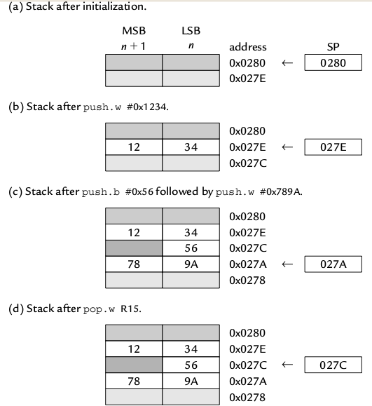
In MSP 430, the top of the RAM (12b bytes) is initially allotted to the stack pointer. Further writings into the stack are performed at lower addresses (goes downwards).
Also, the lsb of a stack address is always hardwired to zero, i.e., stack addresses always point to words. If only a byte is written into the stack, then one byte will be wasted to preserve this alignment.

In assembly language, after a reset, the stack pointer must be explicitly initialized to 0x280.


Predecrement addressing (Pushing) - To insert a new value into the stack, first the stack pointer is decremented by 2, then writing is performed.
Postincrement addressing (Popping) - To delete the current value in the stack pointer, first the value is deleted, then the stack pointer is incremented by 2.

Fig 3. Basic stack operations in MSP430

Status Register (SR)

Fig 4. The Status Register
N - Negative Flag
Z - Zero Flag
C - Carry flag
V - Signed Overflow Flag
GIE - General Interupt Enable
SCG1, SCG0, OSC OFF, CPU OFF - Control of Low Power Modes


The SR also acts as constant generator CG0.


Constant Generator (CG0, CG1)
Both R2 and R3 are used to generate 6 most frequently used constants. This saves fetching time. The constant generated depends on the addressing mode used.

General Purpose Registers
There are 12 of them, R4 - R15. They can be used to store address or data, since both are 16 bit in the MSP430 family. This leads to considerable simplification in the operations.

The MSP-EXP430G2 Development Board

First of all, thanks to Pramode Sir for allowing me to lay my hands on this beauty !!!

The MSP-EXP430G2 Texas Instruments (TI) Launchpad is a $4.30 (only!) Development Board for the MSP430 family from Texas Instruments (TI).

The 14 pin DIP chip shown in the pictures is a MSP430G2231.

Fig 1. Top Side View.


Overview

The original MSP430 was introduced in the late 1990's. In its currrent form, it is a decent midrocontroller with a 16-bit processor having von-Neumann architecture. It is primarily designed for low power applications.

MSP430 is a 16-bit microcontroller, with obviously, a 16 bit data bus and a 16 bit address bus. Its address space is therefore, 2^16 = 64KB of memory. The registers in its CPU are also 16 bit. Hence, machine language instructions can be used with ease whether it be local variables, address or data. Note that MSP430X has extended registers, and a wider address bus and can handle upto 1 MB of memory.

It can be said to be a RISC, but unlike a pure "RISC", it can perform arithmetic operations directly on values in memory. Overall, the MSP430 is one of the simplest microcontrollers from Texas Instruments (TI).

Fig 2. Side View.

Its all in the name ...

The name MSP stands for Mixed Signal Processor (MSP). It indicates that the device can take analog signals as input, and there are also analog to digital converters with a resolution of upto 16 bits.

The letter after MSP430 shows the type of memory.
    F - Flash memory
    C - ROM

For ASSPs, there is a second letter, to indicate the type of measurement.
    E - electricity
    W - water
    G - signals with a gain stage and op-amps in-between

Next digit shows family, and final 2 or 3 digits identify the specific device.

Fig 3. Top Front View.

Features
  • A very small and efficient CPU with 16 bit registers.
  • Specially designed low power modes.
  • No special instructions are needed to put the device in a low-power mode. The mode is controlled by the respective bits in the status register. If an interrupt occurs, MSP430 awakens and returns back to the low power mode smoothly, after the particular interrupt has been serviced. 
  • There is an internal Digitally Controlled Oscillator (DCO) which clocks the CPU. It is capable of restarting in 1 us, thus making the device to wake up from standby or return to low power mode very quickly.
  • There are various low power modes, differing in how much area of the device is active, and how long it takes to restart.
  • It is compatible with a wide range of peripherals used for various purpos
  • It can drive Liquid Crystal Displays (LCD) directly.
  • Some are classified as Application Specific Standard Products (ASSP), and used for specialized purposes. 

Thursday, October 21, 2010

Common Subexpression Elimination (CSE) by GCC

Test Program

    main()
        {
             int i, j, k, r;
             scanf("%d%d", &i, &j);

             k = i + j + 10;
             r = i + j + 30;  

             printf("%d %d %d\n", k, r);
        }

Assemly Code

AT&T format of assembly code is used.
  
    main:
            pushl   %ebp
            movl    %esp, %ebp
            andl    $-16, %esp
            subl    $32, %esp
            leal    24(%esp), %eax
            movl    %eax, 8(%esp)
            leal    28(%esp), %eax
            movl    %eax, 4(%esp)
            movl    $.LC0, (%esp)
            call    scanf
            movl    28(%esp), %edx
            movl    24(%esp), %eax
                leal    (%edx,%eax), %eax
                addl    $10, %eax
                movl    %eax, 20(%esp)
            movl    28(%esp), %edx
            movl    24(%esp), %eax
                leal    (%edx,%eax), %eax
                addl    $30, %eax
                movl    %eax, 16(%esp)
            movl    16(%esp), %eax
            movl    %eax, 8(%esp)
            movl    20(%esp), %eax
            movl    %eax, 4(%esp)
            movl    $.LC1, (%esp)
            call    printf
            leave
            ret

The two blocks in bold represents the evaluation of 'k' and 'r' in the test program respectively.
The 'leal    (%edx,%eax), %eax' command adds the two values in the 'edx' and 'eax' and stores the result in 'eax'. The 'addl' command adds a constant to the value in the 'eax'.
Here, both 'leal' and 'addl' are called two times, for the evaluation of 'k' and 'r' respectively.

 After optimization as:
    gcc -S -O3 -fomit-frame-pointer opt2.c
    less opt2.s

    main:
            pushl   %ebp
            movl    %esp, %ebp
            andl    $-16, %esp
            subl    $32, %esp
            leal    24(%esp), %eax
            movl    %eax, 8(%esp)
            leal    28(%esp), %eax
            movl    %eax, 4(%esp)
            movl    $.LC0, (%esp)
            call    scanf
                movl    24(%esp), %eax
                addl    28(%esp), %eax
                movl    $.LC1, (%esp)
                leal    30(%eax), %edx
                addl    $10, %eax
            movl    %edx, 8(%esp)
            movl    %eax, 4(%esp)
            call    printf
            leave
            ret

Here, what is seen to be done is:
1)
 
'i' in the test program stored in 'eax'


2) 'j' added to 'eax'


        Now 'eax' contains 'i' + 'j'.


3) 'r' is obtained as " 30 + the value in 'eax' "


4) 'k' is obtained by adding 10 to the value in 'eax'

Observation is:
        'i' + 'j' was evaluated only once !

Common Subexpression Evaluation (CSE)

As observed, CSE is an optimization technique employed by the compiler, when the same subexpression is present in more than one expressions.

It is as if the subexpression is evaluated first, and the result is stored in a temporary variable. For all further calculations where this subexpression was a part originally, the value of this newly created temporary variable will be used.
In the test program used above, the so evaluated subexpression is ' i + j '.

Also, CSE is performed only when, in that environment, the cost to use such a temporary variable is lesser than the cost to perform the operations in the subexpression itself. Here, the operation is '+'. 

Tuesday, October 19, 2010

Depicting Function Inlining by GCC

Inline Function

In C, if a particular function used has only a few lines in its body, and if the optimization level is set to 03 (preferably), some unexpected changes can be observed about how gcc handles this function.

What the compiler will do is that it replaces the call for this function, with the actual code of the function, called inlining.

The limit on the number of lines below which inlining is performed, strictly depends upon the gcc heuristics.

This is not all. In  the extreme case, if the small function mentioned above only does something like calculating a value after taking an input, then gcc will evaluate the function call, calculate the value, and directly paste it in the program instead of the function call itself.

Sweet, isn't it?  

Test Program


    int sqr(int x)
        {
            int a;
            return x*x;
        }

    main()
        {
            printf("%d\n", sqr(10));
        }

Assembly Code

To view the assembly code.
    gcc -S -fomit-frame-pointer opt1.c

    less opt1.s


The assembly code is:
    sqr:
            subl    $16, %esp
            movl    20(%esp), %eax
            imull   20(%esp), %eax
            addl    $16, %esp
            ret
          
    main:
            pushl   %ebp
            movl    %esp, %ebp
            andl    $-16, %esp
            subl    $16, %esp
            movl    $10, (%esp)
            call    sqr
            movl    %eax, 4(%esp)
            movl    $.LC0, (%esp)
            call    printf
            leave
            ret
          
On optimization,

    gcc -S -O3 -fomit-frame-pointer opt1.c

        less opt1.s

The new code is:

    sqr:
            movl    4(%esp), %eax
            imull   %eax, %eax
            ret
    main:
            pushl   %ebp
            movl    %esp, %ebp
            andl    $-16, %esp
            subl    $16, %esp
            movl    $100, 4(%esp)
            movl    $.LC0, (%esp)
            call    printf
            leave
            ret

Here, the function sqr( ) does something very simple, and the input to the function is statically assigned. It means that the value of the input (10) will never change during runtime. Hence, the compiler will optimize the program even further, to the extreme that the square of 10 will be evaluated and the result pasted in the program instead of the original call to the function sqr( ).  

Sunday, October 17, 2010

User Mode Linux Built From Scratch !!!

Linux From Scratch
"Linux From Scratch (LFS) is a project that provides you with step-by-step instructions for building your own custom Linux system, entirely from source code."
Homepage is : http://www.linuxfromscratch.org/ .

Use Mode Linux
"User-Mode Linux is a safe, secure way of running Linux versions and Linux processes. Run buggy software, experiment with new Linux kernels or distributions, and poke around in the internals of Linux, all without risking your main Linux setup.
User-Mode Linux gives you a virtual machine that may have more hardware and software virtual resources than your actual, physical computer. Disk storage for the virtual machine is entirely contained inside a single file on your physical machine. You can assign your virtual machine only the hardware access you want it to have. With properly limited access, nothing you do on the virtual machine can change or damage your real computer, or its software."

UML - The kernel on top of a kernel 

To get the complete idea, it is true that the UML kernel can be booted and shutdown from your Linux system, just like another application. It will not cause your Linux system to halt in any way.

How is the required privilege levels setup for the UML kernel?
The privilege levels in a Linux system ranges from 0 (ring 0) to 3 (ring 3). Ring 0 gives you complete power. You can change the contents of any register, do anything. Ring 3 is the user mode. It also has the lowest privilege.

This is the same in the UML kernel too.

Can a C code get privilege level 0?
Yes it can. Through system calls. But it cannot be allowed just like that. Allowing a C code full control will be like allowing viruses to grow in Linux! The C code must be able to make system calls, and simultaneously not be the one who is in possession of the control flow.

This is the specific design technique employed in Linux. When a system call occurs in a C code, there will be a switching from ring 0 to ring 3. It will be simultaneously accompanied with transfer of control from the C program to the Linux kernel. No hassle there.

Thus, total safety is ensured.

How is the UML kernel designed then?
A Linux kernel comprises of two parts:
1) the hardware dependent part - specifically, everything inside the 'arch'
                                                    folder in the kernel source code.
2) others

What is done in the UML kernel is that:
1) take away all the hardware dependent part of the kernel.
2) simply replace it with the system calls of the kernel layer below
    it (pure C code).
    (the UML kernel will behave just as an application)

Consider a sample executable binary 'a.out' compiled inside the UML kernel, from a sample file 'a.c'.

Fig 1. The kernel layers

a.out makes a system call
e.g. read( )


replace a.out's call with the address of
its own read( )


The mechanism:
The UML kernel uses ptrace( ) to freeze 'a.out', the moment it invokes a system call. Then, the address of this function call is replaced with a corresponding system call address that is part of the UML kernel itself.

Everything works fine, in a cute way.

Compiling and Booting the UML kernel

While compiling the kernel, just add an extra parameter 'ARCH=um' to all the steps outlined in the Linux kernel README.
After compilation, an executable binary called 'linux' will be created.

Assuming 'linux' is present in your current directory, to boot into the UML kernel give the command as:
    ./linux ubda=< path of the filesystem >

where filesystem can be a physical partition, or one created with the dd and mkfs/mke2fs commands.

Some Snapshots

'Make'ing Glibc 
Fig 2. Running 'make' for glibc
 'Configure'ing Bash
Fig 3. 'Config'uring Bash
Linguistic Perl 
    The configuration settings for Perl, created by Larry Wall, was the most "linguistic" out of these!  Some excerpts are:


Fig 4. Excerpts from the 'configure' settings for Perl5

Man pages


    These had a 'make install' with one of the shortest SBU, and looked a bit of a variety too!

Fig 5. 'make install' of man pages
Bash without name !
    During the process, there is a time when 'chroot' is used to completely move into the LFS installation and start using the programs already setup inside it.  At this point, the Bash will be setup without creating the /etc/passwd file. Now the Bash will say that it has no name !
Fig 6. Bash without /etc/passwd
After the Bash has been recompiled and installed properly with respect to the LFS system, and the /etc/passwd file created, the Bash prompt reverts back to normal.
Fig 7. Bash after recompiling and creating /etc/passwd
Booting in ...
Fig 8. Booting into the UML kernel
Powering off ...
Fig 9. Powering off the UML kernel

Thursday, October 14, 2010

The AVL Tree

BINARY TREE

A binary tree is a tree data structure in which each node has atmost two child nodes. The child nodes may contain references to their parent nodes. There is a root node, which has atmost two children but no parent.

According to Graph Theory, a binary tree can be also said to be a connected, acyclic graph data structure, with a maximum degree of three for each vertex.

TERMS ASSOCIATED WITH A BINARY TREE
  • The root node of a tree is the node with no parents. There is at most one root node in a rooted tree.
  • A node with no children is called leaf node.
  • The depth of a node is the length of the path from the node to the root. All nodes at the same depth are said to be in the same level. The root node is at level 0.
  • The height of a tree is the length of the path from the node which has the highest depth, to the root node.
  • The children of the same parent are called siblings.
  • A node is an ancestor of another node, if it comes in the path traced from the other node to the root.
  • A node is the descendant of another node, if it is the child of the other node, at some level from it.
  • The size of a node is the number of descendants it has including itself.
  1. A perfect binary tree is a full binary tree in which all leaves are at the same depth or same level. (This is ambiguously also called a complete binary tree.)
  2. A complete binary tree is a binary tree in which every level, except possibly the last, is completely filled, and all nodes are as far left as possible.
  3. A balanced binary tree is where the depth of all the leaves differs by at most 1. This depth is equal to the integer part of log2(n) where n is the number of nodes on the balanced tree.
BINARY SEARCH TREE

A binary search tree is a binary tree in which the numerical value of the data field of the left child is lesser than that of the parent, which is in turn lesser than that of the right child. In short,
(data of left child) < (data of parent) < (data of right child) [numerical value of data is taken]
For example,

Here, in both the trees, data is input in the same order, i.e, 34, 43, 56, 21. Searching in the binary tree is evidently very easier in the BST, hence the name binary search tree.

Each node in a binary search tree can be represented by a structure in C, created with the 'struct' keyword, typically named 'node'. In the most simple case, the data field is taken as an integer. There are three pointers associated with each node, whose typical names can be parent, lchild and rchild, of type 'struct node' itself. These three pointers also make the structure 'node' a self-referential data structure. Obviously, the parent pointer in the structure representing the root node, will be NULL.

The definition for each node will be:
struct node {
int data;
struct node *parent;
struct node *lchild;
struct node *rchild;
};

The names for the fields are self explanatory, and arbitrarily taken.
(The 'parent' pointer points to the parent of a node. It is necessary in an AVL tree only.)

BASIC FUNCTIONS FOR THE BST

Since the binary search tree is a dynamic data structure, the malloc() and free() C standard library functions are used to allocate memory for new nodes while insertion, and to deallocate memory while deleting nodes, respectively. Only the following basic functions are needed to implement the full functionalities associated with a BST.

Constructor -> For creating a new node in the BST
Insert -> For inserting the new node into the BST and
                                           setting up the links
Traverse Inorder -> For inorder traversal through the BST
                                           (for each node, print LnR)
Traverse Preorder -> For preorder traversal through the BST
                                           (for each node, print nLR)
Traverse Postorder -> For postorder traversal through the BST
                                           (for each node, print LRn)
Find                        -> For returning the node whose data field is the
                                            given numerical value
Delete -> For deleting a node from the BST.

where 'n' denotes the current node, 'L' the left child, and 'R' the right child. (thanks to Shijith for this one ...)

N.B. For deletion, if the node is a leaf, just delete it. Otherwise, if the node
         has a right child, replace the node with its successor node in the
         inorder representation of the BST. Else, replace the node with its
         predecessor in the same inorder representation.

BALANCING A BST

The BST seems efficient in searching for a particular data. But it is not so always. When there are large number of nodes, there is the possibility that a devastating situation, as shown below, may occur.

In the second BST, data was input in the order 21, 20, 34, 37, 43, 56. Hence, the structure. According to the BST terminology, a structure like this is said to be unbalanced.

N.B. A BST is said to be balanced, when the depth of any two leaves in
         the BST differs atmost by 1. Also, a balanced tree will be
         theoretically more efficient in all situations, while an unbalanced tree
         will be not.

Why is an unbalanced BST inefficient? For mainly two reasons.
1) The time complexity for searching some data values becomes much
    greater than expected. For example, in the first BST, 43 can be found in
    two steps of traversal. In the second one, it takes an unexpected 4 steps.
    For very large BSTs, the time complexity increases drastically.
2) The lesser the number of levels in the tree, the more efficient the storage.
    When operations like deletion are performed on large BSTs, there is
    a high possibility that the actual addresses of the nodes are spread out
    over a large area of the storage memory (secondary memory).

How to balance a BST?
There are many techniques available, but in all of them, the simple rule is to keep the difference between the depth of any two leaves atmost 1. The BST can be balanced at a particular point in time as desired, or it can be done while insertion into and deletion from the BST. Such BSTs that do "balanced" insertion and "balanced" deletion are called self-balancing binary search trees.

THE AVL TREE

The AVL tree is one of the many kinds of a self-balancing binary search tree. It was invented by G. M. Adelson-Velskii amd E. M. Landis.

Short Bio of the Inventors
G. M. Adelson-Velskii
Georgy Maximovich Adelson-Velskii, was born on 8 January, 1922 in Samara, Russia. He is a Soviet mathematician and computer scientist. Along with E.M. Landis, he invented the AVL tree ("AV" in "AVL" tree stands for Adelson-Velskii) in 1962.
In 1965, he headed the development of a computer chess program, which evolved into Kaissa, the first world computer chess champion.
He currently resides in Ashdod, Israel.

E. M. Landis
Evgenii Mikhailovich Landis, was born on October 6, 1921, in Kharkiv, Ukrainian SSR, Soviet Union. He was a Soviet mathematician who worked mainly on partial differential equations.  He studied and worked at the Moscow State University.
With Georgy Adelson-Velsky, he invented the AVL tree datastructure ("L" in "AVL" stands for Landis).
He died in Moscow on December 12, 1997.

The Technique

The BST can be easily remodelled into an AVL tree by adding some extra functions that perform balanced insertion and balanced deletion. Some other helper functions that perform some trivial tasks are also needed. The balancing is done by a technique called "rotation".

What is rotation?
It can be best illustrated only pictorially. There are two ways to rotate.

i. Right Rotation                    

What happened simply looks as if:
1) node 34 was kept fixed as a "pivot".
2) 34's right child was rotated clockwise about the pivot (node 34 here).
3) there is a change in some links of 34 and 43.

On generalising,

ii.Left Rotation                    

What happened simply looks as if:
1) node 37 was kept fixed as a "pivot".
2) 37's left child was rotated anti-clockwise about the pivot (node 37 here).
3) there is a change in some links of 21 and 37.

On generalising,

N.B. In both cases, the structure of the original BST will be changed to
         that after the rotation. The rule for a balanced tree will be obeyed
         in both the new structures.

Above mentioned are the two ways to perform rotation. When and how many times to perform them depend on the actual arrangement of the nodes in the BST. There are four distinguishable imbalance patterns which occur repeatedly in a BST strucuture. These four patterns are recognized by finding out the "balancing factor" for each node. According to the balancing factor thus obtained, the proper sequence of rotations can be initiated.

What is the balancing factor?
For any node in the BST, its balancing factor is given as:
BF (node) = (height of its left subtree) - (height of its right subtree)

(It can be taken the other way round too, but appropriate sign changes have to be made in the balancing factor of nodes.)  
BF (node 43) = +2
BF (node 34) = +1
BF (node 21) = +1
BF (node 20) = 0 (leaf)

The balancing factor of any node in a balnced BST will be an integer, in the range -1 to +1, including them. If the balancing factor of a node is found to be -2 or +2, it indicates that the BST is unbalanced at that node.
Next, the proper imbalance pattern is identified. Once it is done, the appropriate sequence of rotations are performed.  

THE FOUR CASES OF IMBALANCE

For any number of nodes in a BST, only 4 patterns occur repeatedly. They are classified as the four cases according to which different sequences of left or right rotation or both must be performed. The four cases are:

    LEGEND:
1 - node with BF +2 or -2, indicating need for rotation
parent              - the parent link of node 1
lroot and rroot - the nodes which get "rotated" during each of the left
                             or right rotations respectively
pivot                 - the pivot node in a rotation

From the above figure,
LEFT - LEFT CASE : BF of a node is +2, BF of its left child is +1 or 0
LEFT - RIGHT CASE : BF of a node is +2, BF of its left child is -1
RIGHT - RIGHT CASE : BF of a node is -2, BF of its right child is 0 or -1
RIGHT - LEFT CASE : BF of a node is -2, BF of its right child is +1

Also,
LEFT - LEFT CASE : 1 right rotation
LEFT - RIGHT CASE : 1 left rotation, then 1 right rotation
RIGHT - RIGHT CASE : 1 left rotation
RIGHT - LEFT CASE : 1 right rotation, then 1 left rotation

AVL-SPECIFIC FUNCTIONS

Balancing Factor -> Finds the balancing factor for the given node.
Left Rotation -> Perform left rotation, given a "pivot" and "lroot".
Right Rotation -> Perform right rotation, given a "pivot" and "rroot".
Balance -> Check balancing factor of given node. If the tree is
                                       unbalanced at this node, identify the imbalance
                                       pattern and perform rotation.
Balanced Insert -> Insert a new node, then travel from its parent to the
                                       root, calling Balance() for each node in the path.
Balanced Delete -> Delete the node, then travel from its parent to the
                                       root, calling Balance() for each node in the path.
                                       If the deleted node was not a leaf, the path starts
                                       from the replaced node itself.
                                    
Special Conditions to be Checked while Retracing in Balanced Deletion

If at some node, its BF is:
+1 or -1 : it indicates that the height of the subtree has remained unchanged,
                and retracing can stop.
0            : height of the subtree has decreased by 1, and retracing needs to
                continue.
+2 or -2 : needs rotation.
                If BF of the node after rotation is 0, continue retracing since
                height of this subtree has again decreased by 1.

N.B. In insertion, if the BF of a node after rotation is 0, it indicates that the
         height of that subtree has remained unchanged, contrary to the similar
         situation while deletion.

CONCLUSION
Once the above extra functions are defined, the BST will be remodelled into an AVL tree.