 |
| Fig 1. The MSP430 LaunchPad from TI |
The registers in MSP430 are:
 |
| Fig 2. The registers in MSP430 |
Program Counter (PC)
The program counter stores the address of the instruction which is to be executed next.
For the execution of each instruction, first the address stored in the PC is placed in the address bus. Then, the instruction stored in this address is fetched. Meanwhile, the PC is automatically incremented by 2, i.e, PC now contains the address of the next instruction. The current instruction is now executed, and the next instruction fetched simultaneously.
This is the normal procedure, unless a jump instruction is encountered. In such cases, the PC is incremented by an offset contained in the opcode of the jump instruction. For interrupts and subroutines, the return address needs to be stored in the stack pointer before jumping.
An instruction comprises of 1-3 words, which are aligned to even addresses. So the LSB is hardwired to zero.
Stack Pointer (SP)
In MSP 430, the top of the RAM (12b bytes) is initially allotted to the stack pointer. Further writings into the stack are performed at lower addresses (goes downwards).
Also, the lsb of a stack address is always hardwired to zero, i.e., stack addresses always point to words. If only a byte is written into the stack, then one byte will be wasted to preserve this alignment.
In assembly language, after a reset, the stack pointer must be explicitly initialized to 0x280.
Predecrement addressing (Pushing) - To insert a new value into the stack, first the stack pointer is decremented by 2, then writing is performed.
Postincrement addressing (Popping) - To delete the current value in the stack pointer, first the value is deleted, then the stack pointer is incremented by 2.
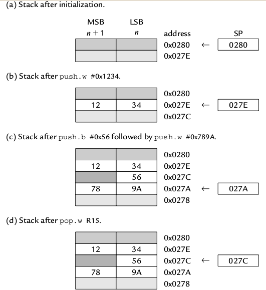 |
| Fig 3. Basic stack operations in MSP430 |
Status Register (SR)
| Fig 4. The Status Register |
Z - Zero Flag
C - Carry flag
V - Signed Overflow Flag
GIE - General Interupt Enable
SCG1, SCG0, OSC OFF, CPU OFF - Control of Low Power Modes
The SR also acts as constant generator CG0.
Constant Generator (CG0, CG1)
Both R2 and R3 are used to generate 6 most frequently used constants. This saves fetching time. The constant generated depends on the addressing mode used.
General Purpose Registers
There are 12 of them, R4 - R15. They can be used to store address or data, since both are 16 bit in the MSP430 family. This leads to considerable simplification in the operations.
No comments:
Post a Comment