Thursday, November 4, 2010

Analysing Jump Tables in MSP430 Assembly Code

Jump Table

A jump table is an array of pointers to functions or an array of assembly code jump instructions. 

In assembling, jump tables are the most efficient method to handle switch statements with a large number of cases. The jump table is created only once and the required field in the table can be accessed simply by indexing.

Especially in embedded systems, where there is a heavy constraint in available memory, jump tables can be efficient while consuming lesser memory too.

Sample Program

Fig 1. Sample Program
The switch has only four cases, hence there is no need for a jump table. The cases are implemented simply as:
Fig 2. The switch implementation without jump table
The behavior is almost as expected.
Now, I need a switch with enough cases, to get the attention of the gcc compiler heuristics.
Fig 3. More cases for the switch
I have to check the corresponding assembly code generated for the above program, to be sure.
Fig 4. Lookup table created - PartI
Fig 5. Lookup table created - PartII
 It worked, the compiler decided that a jump table is really essential now.

The "mov #1,@r4" line stores the value of variable "i". There are 8 cases, numbered from 0 to 7. Hence first "i", i.e, @r4 is compared with 8, for obvious reasons.

Analysing the 'jump table'

The jump table has been created, starting from the address denoted by the label ".L11".

The first entry in the table holds label ".L3" which is the starting address  of the block of statements under "case 0:".
The next entry is ".L4", which is the starting address of the block of statements under "case 1:".
And so on ... Till "case 7:".
There are 8 ".word"s in the jump table too. Correct!

The line N in the jump table holds the starting address of the block of statements under the corresponding "case N:". In other words, each line is the offset to be added to ".L11", to execute the required case statements.

Decoding ...

"r15" holds the value to be switched.

"rla r15" rotates left arithmetically the value inside r15, once (multiplication by 2).
Remember that even addressing is required for MSP430 family.

"add #.L11,r15" adds the present value of "r15" (similar to offset), with the address of the  label ".L11" (similar to base address).
"r15" now contains the address of the line that lies at the given offset from ".L11".

After the "mov @r15,r15" line, "r15" now contains the starting address of a block of statements under the selected "case".

"br r15" simply branches to the address pointed to by r15.

Clean.

Issues
  • How can you justify that jump tables are friendly to embedded systems?
Its true that a jump table has a particular overhead for itself.

Suppose there are a very large number of switch cases. Then, this "jump to index" overhead will be much lower than the cost to perform N case comparisons. That is why jump tables are usually preferred.
  • Jump tables work only when the case identifiers are consecutive.
For example, case 1, case 2, case 3, etc ...

In situations where the cases are random and spread over a large range, suitable searching methods are needed. Normally, binary search is used. The correct case can then be selected in 3 or 4 steps without performing N comparisons each time.

Wednesday, November 3, 2010

Assembling in MSP430G2231

Sample Program

mov #0x0260,r5
mov #0x0270,r6

    Loop:
cmp #0,@r5
jz End
mov @r5,@r6
incd r5
incd r6
jmp Loop

    End:
mov #0x01,&0x22
mov #0x01,&0x21

This code demonstrates a simple implementation of 'strcpy' in msp430 assembly code. The first string is present in the location 0x0260. It is to be copied to another memory location starting from 0x0270. The RAM area of MSP430G2231 lies in the range 0x0200 to 0x027F.

Whats worth noticing is the ease with which some operations are defined which are otherwise very difficult in other assembly codes.

The program exits gracefully by lighting the red led, after successfully copying the string.

Notations

# - This symbol is used to indicate a pure number. The
      number can be an integer, in binary or a
      hexadecimal.
      For example, "mov #0x0260,r5" will move the hex
      number 0260 to register r5.

@ - It can happen that, the data stored in a register is
      the address of another memory location. The actual
      value inside this address can be accessed by using
      the '@' symbol. When '@' is used, the value in a
      register is interpreted to be the address of a memory
      location, and the actual data present in this location
      is fetched.
      The line "cmp #0,@r5" compares the number 0 with
      the data in the memory location pointed to by the
      value of r5.

& - When the address of a location is to be used directly,
      the '&' symbol is used. If not, the address is
      interpreted as just a number, thereby generating errors.

Notable Feature

@ and again @
    The line "mov @r5,@r6" is simple, sleek, easy-to-understand, self explanatory and normally illegal in other assembly languages.

    Technically, the '@' operation is emulated for the destination part. The "mov @r5,@r6" line will be changed to "mov @r5,0x0(r6)" after running msp430-gcc.

Conclusion
The MSP-EXP430G2 Launchpad (TI) for the MSP430 family
Altogether, there are only 27 instructions with about 7 addressing modes in the MSP430 family, which are easy to grasp and employ.
  
Coding in MSP430 family is fun!

Tuesday, October 26, 2010

Remote Debugging the MSP-EXP430G2 LaunchPad from TI

Remote Debugging in GDB

There is an inbuilt ability for gdb to also debug programs that reside in remote machines using a gdb-specific protocol. The remote machine is connected to the host via a serial line, or through a port. This remote connection is called a gdb proxy.

While inside gdb, give as:
    (gdb) target remote localhost:2000

This would enable gdb to perform all debugging operations on a program connected to the localhost machine through the port 2000.

There is a prerequisite that the machine that is to be present in the same port must have set permissions for an external debugger.

Sample Program

Fig 1. Sample program - led1.c
This sample program named 'led1.c', is only used to demonstrate remote debugging.

The Preparation

Connect the LaunchPad to the system. Now the sample program is cross-compiled, and downloaded into the LaunchPad.
For further details, refer:
switching-on-launchpad-leds.html

For necessary reasons, I am calling the current terminal, "Terminal1".

The 'mspdebug' has a built-in command that enables it to run a GDB remote stub on a specified TCP/IP port. If no port is specified, 2000 is taken as default.

Give as:
    (mspdebug) gdb

A message will be displayed as:
    Bound to port 2000. Now waiting for connection...

At this time, open another terminal. I'm calling it "Terminal2".
In Terminal2, give as:
    msp430-gdb -q a.out

Here, 'a.out' is the LaunchPad-specific executable binary obtained by cross-compiling the above sample program.

Now, connect to the remote machine already waiting in port 2000 as:
    (gdb) target remote localhost:2000

An acknowledgement message will be displayed as:
    Remote debugging using localhost:2000
    0x0000fc00 in _reset_vector__ ()

If you check back in Terminal1, messages similar to the following will have been displayed:
    Client connected from 127.0.0.1:47558
    Clearing all breakpoints...
    Reading 2 bytes from 0xfc00

The current states of the two terminals is as shown:
Fig 2. Terminal1 (left side)  and Terminal 2 (right side)
On listing 'led1.c' in Terminal2, the memory addresses from which the bytes are read will be displayed in Terminal1, simultaneously.

Fig 3. Listing the sample program
Fig 4. Single stepping through runtime libraries
On further single steps from this point, the runtime libraries through which the control passes until main( ) is reached, can be observed directly !!!
Notice that a considerable number of bytes have been read.

Now, single step till the instruction 'P1OUT = 0x01' is reached. 

The Action

At this point, the next single step will cause it to execute, which will pass a high voltage (binary 1) to the red led on the LaunchPad, i.e., do it, and see the red LaunchPad led (P1.0) flash bright !!!

On next step, a binary 0 is passed to P1.0, causing it to be off.

Single step again, and see the green LaunchPad led (P1.6) flash before your eyes !!!

Turn it off too, and keep on single stepping, until you relish the wonderful thing thats happening infront of you ... This is GDB at its best !!!
At all these points, the memory addresses from which reading takes place are displayed in Terminal1.

N. B. 
  • Properly exit from both mspdebug in Terminal1 and GDB in Terminal2, before disconnecting the LaunchPad from the system.
  • Exit from GDB in Terminal2 first, and then mspdebug in Terminal1.


Addendum

It was one of the cutest moments, to actually 'see' GDB in work. 
I am crazy on LaunchPad !!! 

Switching on the LaunchPad LEDs ...

Installation

The basic amenities are:
  • mspgcc
  • libusb-dev
  • libreadline-dev
  • mspdebug
After these are installed, msp-430-gcc or msp-430-gcc-4.4.3 can be used to cross-compile the C code.

The 'libusb-dev' library contains necessary libraries for sucessfully connecting the LaunchPad through the USB cable.

The 'libreadline-dev' library is for enabling history for the commands typed inside the 'mspdebug' environment.

Ensure that the LaunchPad has been detected by:
    dmesg | tail

Your LaunchPad will be assigned to the device: /dev/ttyACM0.

The mspdebug is used for interacting with, erasing or burning the flash memory of the MSP chip. It also allows to debug the downloaded program present inside the MSP chip flash memory, through the inbuilt JTAG or Spy-By-Wire support.

The eZ430-RF2500 tool of the mspdebug supports the USB connection and also provides Spy-By-Wire debugging.


Switch on your LEDs !!!  

A sample program led2.c, which lights up both the LEDs on th LaunchPad when the switch S2 on P1.3 is pressed.
Fig 1. The sample program
First, cross-compile the code.
    msp430-gcc-4.4.3 -g led2.c

Now connect the LaunchPad. Then:
    sudo mspdebug rf2500

Fig 2. Inside mspdebug
To download the code, use:
    (mspdebug) prog a.out

Fig 3. Downloading the code
Now run it, as:
    (mspdebug) run
Fig 4. Running the code

The Addressing Modes in the MSP430 Family


Register Mode


mov.w R4,R5 ; move (copy) word from R4 to R6

It is the fastest, with only 1 machine cycle needed.
Any of the 16 registers can be used as source or destination.

Special cases:
  • PC - it will be autoincremented before it is used as source
  • Both PC and SP must be even, because they are always used as words. so  LSB discarded if they are used as destination
  • CG2 - it reads 0 as source
for byte operations:
  • operand is taken from lower byte only
  • writing is performed to lower byte only, upper byte is cleared
To use the upper byte in a regiser as source, 'swpb' may be used.

Indexed Mode 

Similar to arrays.

mov.b 3(R5),R6 ; load byte from address 3+(R5) into R6

Here, base address is 3.
Indexing can be used for the source or destination part.

Symbolic Mode (PC Relative)

When PC is used as the base address in the indexed mode, its called symbolic mode by TI. The offset to be added to the PC is given as the constant.

mov.w Loop,R6 ; load word Loop into R6

Assembler replaces this as:

mov.w X(PC),R6 ;

where X = Loop - PC, is the offset in this case. It is caluclated by the assembler, which also performs autoincrementing of PC.

In MSP430, absolute addressing can reach all the memory map. The symbolic mode is mainly meant for MSP430X, etc.

Absolute Mode

This is a special case where the constant in the indexed mode is the absolute address of the data. Since the constant is already the final address, the base must be taken as an address of 0. Usually the SR is selected for this purpose. It behaves as 0 when used as the base, i.e, this is one instance when the SR behaves as a constant generator (CG1).

Absolute addressing is shown by the prefix &.

mov.b P1IN,R6 ; load byte P1IN into R6

It is replaced by the assembler as:

mov.b P1IN(SR),R6 ;

P1IN is the offset, and SR behaves as 0.

SP-Relative

This is not a separate mode in itself. At any time, any value pushed into the stack previously can be accessed, by offseting a suitable amount from the SP. For example:

mov.w 2(SP),R6 ;

Indirect Register Mode

This is available only for the source. It is indicated by the sign @. It means that the contents of a register is used as the address of the operand, i.e, the register contains a "pointer" to the actual operand.

mov.w @R5,R6 ; load word from address pointed to by R5

This is similar to indexed addressing with base address 0. It saves a word of program memory, hence makes it faster.

This mode cannot be used for destination. Using indexed addressing instead:

mov.w R6,0(R5) ; store word from R6 into address 0+(R5)

There is a penalty that a word 0 must be stored in the program memory, and fetched. The constant generator cannot be used.

Indirect Autoincrement Register Mode

This is also available only for the source. It is indicated by a @ in the front, and a + as suffix. Here, the register is used as a pointer as in the indirect register mode. After this, the value in the register is autoincremented by 1 if a byte has been fetched, or by 2 if a word has been fetched.

mov.w @R5+, R6

Since this mode cannot be used for destination, the indexed addressing mode must be used and then explicitly incrementing the value of the register appropriately. Obviously, two instructions would be required.

N.B.
  • MSP430 only has postincrement addressing.
  • In all the addressing modes, all operations on the first address are fully completed before the second address is evaluated.

Immediate Mode

It is a special case of autoincrement addressing that uses program counter PC. For example:

mov.w @PC+,R6 ;

Here, after the instruction pointed to by PC has been fetched, PC is autoincremented, i.e., PC now points to the next instruction. This particular instruction will be the one copied into R6.

The MSP430 Central Processing Unit

MSP430 has 4 special purpose and 12 general purpose registers.
Fig 1. The MSP430 LaunchPad from TI

The registers in MSP430 are:
Fig 2. The registers in MSP430

Program Counter (PC)

The program counter stores the address of the instruction which is to be executed next.

For the execution of each instruction, first the address stored in the PC is placed in the address bus. Then, the instruction stored in this address is fetched. Meanwhile, the PC is automatically incremented by 2, i.e, PC now contains the address of the next instruction. The current instruction is now executed, and the next instruction fetched simultaneously.

This is the normal procedure, unless a jump instruction is encountered. In such cases, the PC is incremented by an offset contained in the opcode of the jump instruction. For interrupts and subroutines, the return address needs to be stored in the stack pointer before jumping.

An instruction comprises of 1-3 words, which are aligned to even addresses. So the LSB is hardwired to zero.

Stack Pointer (SP)

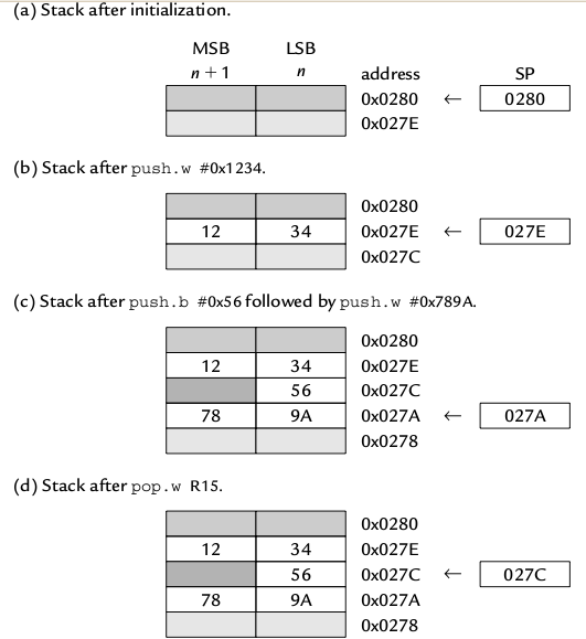
In MSP 430, the top of the RAM (12b bytes) is initially allotted to the stack pointer. Further writings into the stack are performed at lower addresses (goes downwards).
Also, the lsb of a stack address is always hardwired to zero, i.e., stack addresses always point to words. If only a byte is written into the stack, then one byte will be wasted to preserve this alignment.

In assembly language, after a reset, the stack pointer must be explicitly initialized to 0x280.


Predecrement addressing (Pushing) - To insert a new value into the stack, first the stack pointer is decremented by 2, then writing is performed.
Postincrement addressing (Popping) - To delete the current value in the stack pointer, first the value is deleted, then the stack pointer is incremented by 2.

Fig 3. Basic stack operations in MSP430

Status Register (SR)

Fig 4. The Status Register
N - Negative Flag
Z - Zero Flag
C - Carry flag
V - Signed Overflow Flag
GIE - General Interupt Enable
SCG1, SCG0, OSC OFF, CPU OFF - Control of Low Power Modes


The SR also acts as constant generator CG0.


Constant Generator (CG0, CG1)
Both R2 and R3 are used to generate 6 most frequently used constants. This saves fetching time. The constant generated depends on the addressing mode used.

General Purpose Registers
There are 12 of them, R4 - R15. They can be used to store address or data, since both are 16 bit in the MSP430 family. This leads to considerable simplification in the operations.

The MSP-EXP430G2 Development Board

First of all, thanks to Pramode Sir for allowing me to lay my hands on this beauty !!!

The MSP-EXP430G2 Texas Instruments (TI) Launchpad is a $4.30 (only!) Development Board for the MSP430 family from Texas Instruments (TI).

The 14 pin DIP chip shown in the pictures is a MSP430G2231.

Fig 1. Top Side View.


Overview

The original MSP430 was introduced in the late 1990's. In its currrent form, it is a decent midrocontroller with a 16-bit processor having von-Neumann architecture. It is primarily designed for low power applications.

MSP430 is a 16-bit microcontroller, with obviously, a 16 bit data bus and a 16 bit address bus. Its address space is therefore, 2^16 = 64KB of memory. The registers in its CPU are also 16 bit. Hence, machine language instructions can be used with ease whether it be local variables, address or data. Note that MSP430X has extended registers, and a wider address bus and can handle upto 1 MB of memory.

It can be said to be a RISC, but unlike a pure "RISC", it can perform arithmetic operations directly on values in memory. Overall, the MSP430 is one of the simplest microcontrollers from Texas Instruments (TI).

Fig 2. Side View.

Its all in the name ...

The name MSP stands for Mixed Signal Processor (MSP). It indicates that the device can take analog signals as input, and there are also analog to digital converters with a resolution of upto 16 bits.

The letter after MSP430 shows the type of memory.
    F - Flash memory
    C - ROM

For ASSPs, there is a second letter, to indicate the type of measurement.
    E - electricity
    W - water
    G - signals with a gain stage and op-amps in-between

Next digit shows family, and final 2 or 3 digits identify the specific device.

Fig 3. Top Front View.

Features
  • A very small and efficient CPU with 16 bit registers.
  • Specially designed low power modes.
  • No special instructions are needed to put the device in a low-power mode. The mode is controlled by the respective bits in the status register. If an interrupt occurs, MSP430 awakens and returns back to the low power mode smoothly, after the particular interrupt has been serviced. 
  • There is an internal Digitally Controlled Oscillator (DCO) which clocks the CPU. It is capable of restarting in 1 us, thus making the device to wake up from standby or return to low power mode very quickly.
  • There are various low power modes, differing in how much area of the device is active, and how long it takes to restart.
  • It is compatible with a wide range of peripherals used for various purpos
  • It can drive Liquid Crystal Displays (LCD) directly.
  • Some are classified as Application Specific Standard Products (ASSP), and used for specialized purposes.